fill in the appropriate functional names for the digital signal processing system block diagram in the figure. () 为下图所示的数字信号处理系统框图填入适当的功能模块名称:()。
Fill in the appropriate functional names for the digital signal processing system block diagram in the figure. () 为下图所示的数字信号处理系统框图填入适当的功能模块名称:()。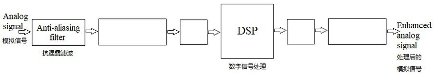
A、(From left to right) Sample-and-hold circuit; ADC; DAC; Reconstruction filter (从左到右)采样保持电路;模数转换器;数模转换器;重建滤波
B、(From left to right) Sample-and-hold circuit; ADC; Reconstruction filter; DAC (从左到右)采样保持电路;模数转换器;重建滤波;数模转换器
C、(From left to right) ADC; Sample-and-hold circuit; DAC; Reconstruction filter (从左到右)模数转换器;采样保持电路;数模转换器;重建滤波
D、(From left to right) Sample-and-hold circuit; DAC; ADC; Reconstruction filter (从左到右)采样保持电路;数模转换器;模数转换器;重建滤波
 题目内容
(请给出正确答案)
题目内容
(请给出正确答案)
 of the system is
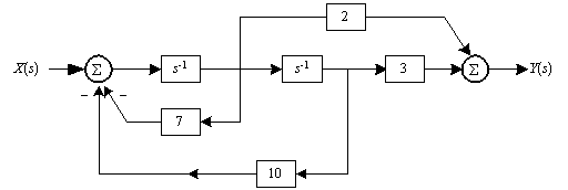


 简答题官方参考答案
(由简答题聘请的专业题库老师提供的解答)
简答题官方参考答案
(由简答题聘请的专业题库老师提供的解答)
 抱歉!暂无答案,正在努力更新中……

 satisfy?


 , in the presences of disturbances.
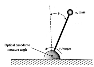
 complex Alamouti's STBC and two transmit antennas. The codeword of STBC for input symbols
 and
and is denoted by
 .with each row corresponding to an antenna and each column corresponding to a timeslot . a) Draw the block diagram of the transmitter. b) If the symbols of the two timeslots in the codeword are input to Subcarriers k, and k+1, respectively, write the received signals on the two subcarriers after OFDM demodulation in the receiver. c) Write the expression of the STBC decoder.